
How Does Precast Overhang Work?
First, let’s bring you up to speed on the idea behind precast bridge decks and their construction techniques...
The bridge deck itself is an element of bridge construction that greatly benefits from the precast overhang construction method. This portion of bridge construction is repetitive as well as costly to construct due to the labor required for formwork placement and removal, the placement of the necessary reinforcement, the placement of the concrete, as well as providing adequate curing.
The bridge deck itself is an element of bridge construction that greatly benefits from the precast overhang construction method. This portion of bridge construction is repetitive as well as costly to construct due to the labor required for formwork placement and removal, the placement of the necessary reinforcement, the placement of the concrete, as well as providing adequate curing.
|
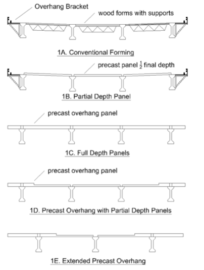
In an effort to improve the economy and construction of bridge decks, several US Department Of Transportation groups began using partial-depth, pre-stressed precast panels as stay-in-place formwork. These panels were typically used in the interior portion of the span and were only half of the bridge deck depth.
Next, mild reinforcing steel was added above these panels and cast-in-place concrete was placed to finish the bridge. While these partial-depth stay-in-place forms yield definite benefits versus conventional construction methods, the cantilever portion of the bridge deck is conventionally formed by using overhang brackets that serve as both formwork and a work platform, as shown in Fig. 1B. Several states adapted the partial-depth system on bridges, helping engineers realize challenges with this method, such as the slowness of overhang construction, the difficulty in obtaining the correct elevation of the finished riding surface, and finishing construction with an inadequate amount of support under each panel, causing serviceability problems. The Texas DOT extensively researched these challenges to procure them, deducing that if the system is constructed correctly it is able to provide an economical bridge deck system with a large amount of reserve capacity. Several states use this system as a standard method of bridge construction due to improvements in safety, economy and speed when compared to conventionally formed bridge deck construction. |
|
Beginning in 1985 several DOTs (Texas, Louisiana, New York, New Jersey, Vermont) started investigating the use of full-depth precast bridge deck systems. Typically, these bridge deck systems consist of thick concrete planks running the entire width of the bridge deck placed on the beams below, as shown in Fig. 1C.
These concrete planks are heavy as well as difficult to transport and place. Once these elements are in place, they are connected with reinforcing steel and some cast in place of grout or concrete. Some systems are then post-tensioned to minimize the amount of cracking in the bridge deck.
There has been a flourish of research over this topic as several states continue to investigate and implement these systems. One benefit these systems have over the partial-depth deck panel system is their removal for the need of conventional forming used in overhang construction.
These systems typically use very little cast-in-place concrete or grout and require the use of several leveling bolts to obtain the correct geometry and riding surface of the bridge deck. While these grade bolts are very useful, it is difficult to provide adequate flexibility to meet the large number of different geometries required for a bridge deck. Furthermore, due to differential camber between prestressed concrete beams, these systems are useable only on steel girders, therefore limiting the use of these systems.
It is often necessary to provide an asphalt wearing surface or grind the surface of the deck elements where the concrete planks interface to obtain the correct riding surface. An example of an unsatisfactory riding surface provided by one of these full depth panel sections can be found in Fig. 2.
While the full-depth precast section has shown an improvement in speed of construction, it has also shown an increase in the cost of construction. This increase can be attributed to large shipping weights, increase in crane size, and additional wear or grinding on the bridge deck surface.
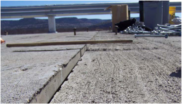
Figure Two: A wooden stick placed at the intersection of two full-depth precast panels adjusted using grade bolts. The difference in panel height is over ¼”.
|
While reviewing the benefits and challenges of the full-depth and partial-depth bridge decks, it was realized some features of both systems could be combined in a hybrid system achieving significant improvements over the previous systems. An overview of this new hybrid system is shown in Fig. 1D.
In this system, a new precast panel is used in the overhang extending from the first interior girder to the tip of the cantilever. This precast panel is full depth from the cantilever tip until the compression zone of the exterior bay. The panel is then only partial depth until the first interior girder. |
Each proportion and size of the precast overhang panel is chosen for specific reasons. The full-depth portion of the precast panel at the exterior of the bridge allows for the removal of the overhang-forming brackets and also provides a platform for construction work, as well as an area for a safety rail. Pockets in this full-depth section are used to provide a connection between the precast panel and the exterior girder.
|
Grout is used to fill the haunch area followed by concrete to fill the pockets. These grout pockets also provide a location for the screed rail to attach to the bridge deck. These panels contain special inset areas in the full-depth section allowing a connection to be made between panels as well as a place for grade bolts for altering panel geometry.
In addition to this panel, a novel adjustable haunch gasket was developed to use with this system. This haunch-forming system is made with low density polyethylene foam glued to the top of the girder allowing it to compress or expand as the grade bolts are adjusted in the precast overhang panel. A detailed summary of the precast overhang element can be found in Figures Three and Four. |
Grout Pouring Detail from Tyler Ley on Vimeo. |
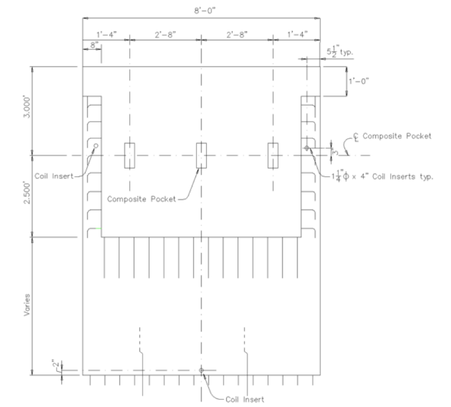
Figure Three: A plan view of the precast overhang panel showing dimensions.
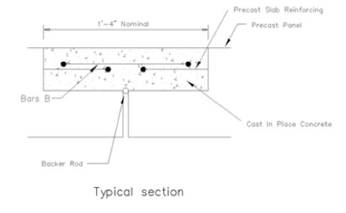
Figure Four A: Connection details between the precast overhang panels.
|
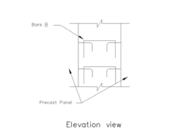
Figure Four B: Connection details between the precast overhang panels
|
For the interior bays, the partial-depth precast panels are used after the geometry of the precast overhang panel is established with grade bolts. The reinforcing steel in the interior span and between panels is placed, and concrete is used in the partial depth section.
Finally, the haunch of the exterior girder is grouted and then the pockets are filled with a low-shrink concrete mixture. The traffic rail for the bridge is then completed, and the deck is finished. A pictorial explanation of the construction process is shown in Fig. 5.
Finally, the haunch of the exterior girder is grouted and then the pockets are filled with a low-shrink concrete mixture. The traffic rail for the bridge is then completed, and the deck is finished. A pictorial explanation of the construction process is shown in Fig. 5.
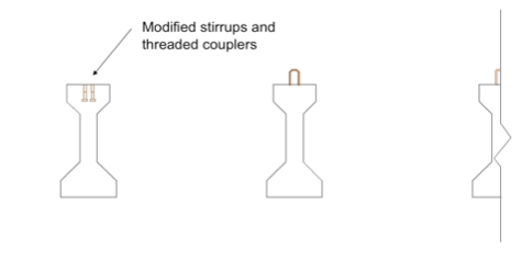
Figure Five A: The beams are erected on the bents. A shear connector is used on the external beam for load transfer.
|
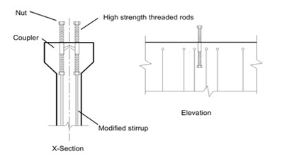
Figure Five B: Structural details for the modification of the external beam.
|
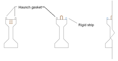
Figure Five C: The haunch gasket is glued to the external girder and the outside face of the interior beam.
|
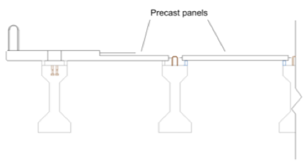
Figure Five D: Precast panels are placed. Precast overhang panels are used in the exterior bay and partial depth panels in the interior bays.
|
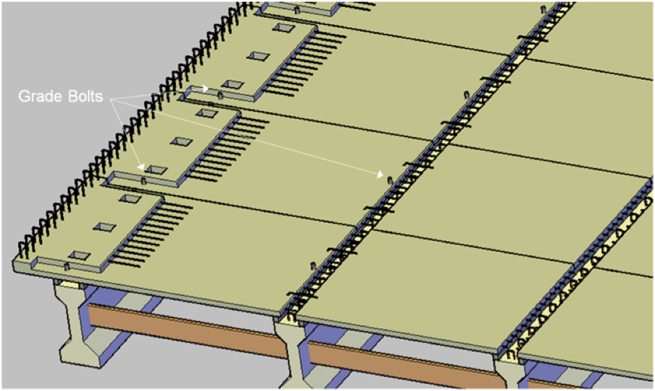
Figure Five E: Grade Bolts are adjusted in the overhang panels to the desired grade.
Grade Bolt Tightening from Tyler Ley on Vimeo.
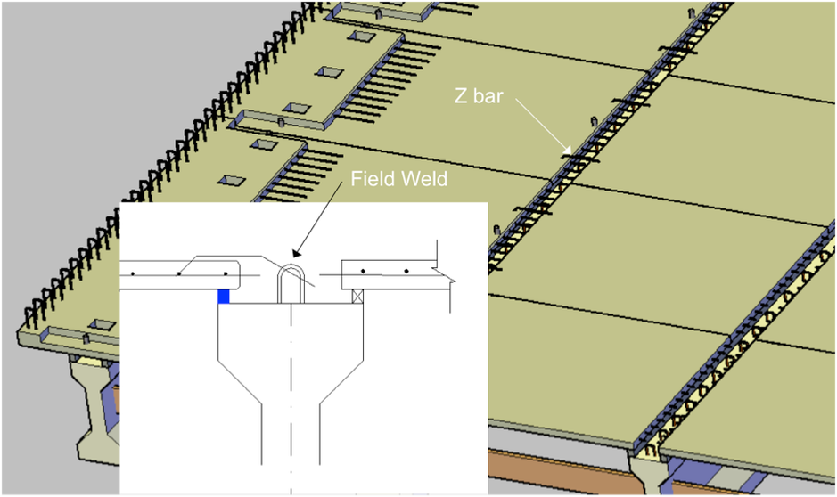
Figure Five F: The external rebar is a failsafe bar bent down and welded to the stirrups of the first interior beam to prevent overturning.
Connection Steel from Tyler Ley on Vimeo.
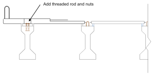
Figure Five G: Threaded rods and nuts are added to the grout pocket of the external beam. This step may be carried out before the paving of the overhang panels.
|
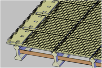
Figure Five H: Rebar is paved above the partial-depth portions of the deck.
|
Tightening Threaded Rods-edit from Tyler Ley on Vimeo.
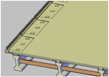
Figure Five I: Concrete is placed to tie the precast system together. The haunch of the external girder is filled with grout, then the composite pockets are filled with concrete.
|
As previously stated, this specific bridge deck system was designed to combine advantageous features from the partial-depth bridge deck with the full-depth bridge deck systems to address the challenges of both systems.
This system adapts the full-depth section of the bridge deck in the overhang portion, eliminating the placement and removal of formwork for the overhang as well as the work platform required for the partial-depth panel system. Furthermore, the full-depth length was sized to create a significant work platform for the screed rail as well as providing construction workers an area to finish the external areas of the bridge deck by hand. The precast panel is designed to continue over the exterior girder, extending to the first interior girder providing a stable support for the panel. |
|
Threaded inserts for the installation of columns contractors use for hand rail/fall protection systems are incorporated into the precast overhang panels, allowing fall protection installation concurrently with the overhang units. While nearly any system can be accommodated, the inserts for the Rock Creek bridge were cast in the top slab approximately 3” from the outside edge (inside the concrete traffic rail footprint). This location prevents patching after the temporary hand rail is removed since the rail concrete covers the inserts.
Grade bolts are used in the precast overhang panel, much like in full depth bridge deck construction techniques, obtaining the desired riding surface. However, the precast overhang system only requires three grade bolts at the exterior bay as this is the only full-depth portion of the bridge deck. By using a set of non-continuous precast panels, the precast overhang method allows the avoidance of past challenges other full-depth precast members encountered where construction tolerances from differential-beam deflections cause grinding or possibly an overlay as shown in Fig. 2. |
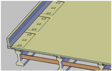
Figure Five J: The concrete barrier is constructed by either slip forming or conventional forming.
|
A not-so-obvious benefit from this method is the simplification of the bridge-deck construction. When the full-depth portion of the precast panel is placed on the exterior beam, it is placing nearly the entire dead load on the outside girder before the placement of the remaining cast-in-place concrete. The placement of this dead load on the external girder ensures the height of the bridge deck established by the grade bolts for the full-depth section will be very close to the final height of the bridge deck because additional dead load deflection can no longer occur. This benefit allows the construction engineer to directly establish the roadway profile to match the desired elevation, ensuring all concrete cover requirements are met.
There are numerous challenges to provide the correct ride and reinforcement cover with partial-depth panel systems as one must accurately determine the deflection of the bridge deck from the placement of the fresh concrete. This is often challenging due to the complex construction geometry and differential beam deflection, especially in the cast of precast concrete girders. As previously mentioned, due to the pre-loading of the external beam this is no longer a problem with the precast overhang system and the desired bridge-deck height is directly established with grade bolts.
There are numerous challenges to provide the correct ride and reinforcement cover with partial-depth panel systems as one must accurately determine the deflection of the bridge deck from the placement of the fresh concrete. This is often challenging due to the complex construction geometry and differential beam deflection, especially in the cast of precast concrete girders. As previously mentioned, due to the pre-loading of the external beam this is no longer a problem with the precast overhang system and the desired bridge-deck height is directly established with grade bolts.